Friday, May 31, 2013

Week 12: Working Arduino

At this stage I now set up a new Arduino circuit and wrote up a new code to control separate 2 DC motors and also to control a full rotation servo.
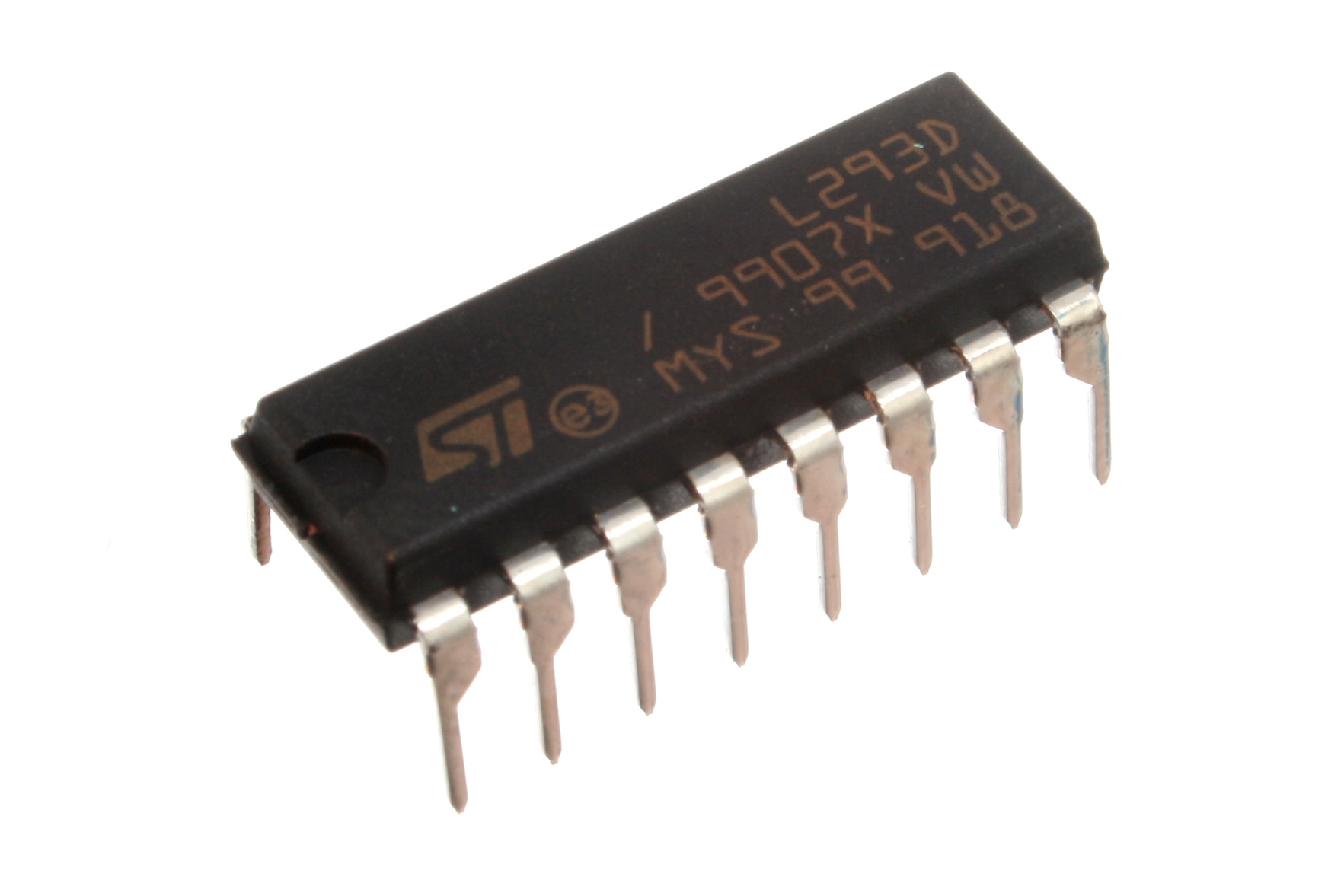
What I have now is the 2 L293D motor driver to control each motor by the push button. There are two push button to control each motor. While one motor is rotating the other will be disabled and while the other is push will work other wise. The reason to separate the two DC motor is becasue of the power supply. In this circuit the power from 9V battery is supplied separately. (See below Diagram)

There are also another push button to control the direction of the full rotation servo. Once the button is pressed servo will rotate clockwise after a set time it will then rotate counter clockwise for a certain seconds

Video below shows how to servo works with the push button.


Another push button is also installed to control the standard servo this one will act as a switch for electromagnet. At this stage we can not find the way to make a magnet stronger. Therefore we will not be putting it in the prototype.

The following is the code applied in the Arduino Application.

#include <Servo.h> //include servos in the code

Servo servoMain; //identify servo as a main servo
Servo servoSwitch; //identify servo as a switch servo for eletromagnet

int switchPin = 1; //push button pin for motor to go left
int switch2Pin = 2; //push button pin for motor to go right

int servoSwitchPin = 4; //push button pin for electrmagnet switch
int mainServoLongPin = 7; //push button pin for main servo to move down
int mainServoUpPin = 8; //push button pin for main servo to move up

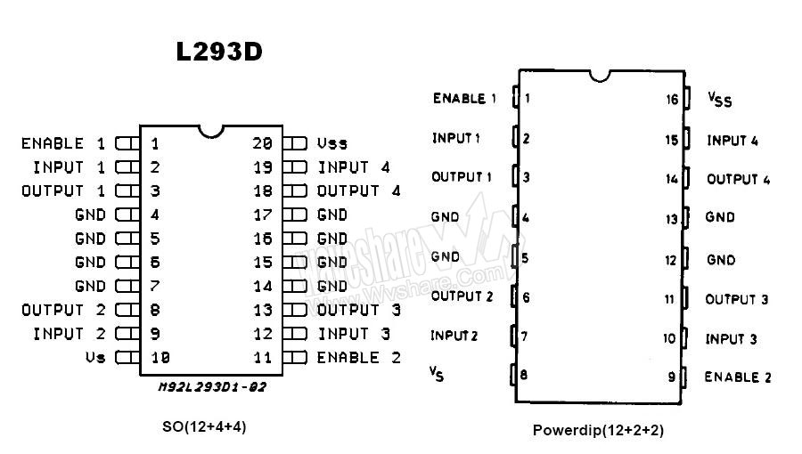
//pin for L293D H-bridge motor drive
//left motor
int motor1Pin1 = 6; // pin 2 on L293D
int motor1Pin2 = 11; // pin 7 on L293D
int enablePin = 5; // pin 1 on L293D

//right motor
int motor2Pin1 = 10; // pin 2 on L293D
int motor2Pin2 = 9; // pin 7 on L293D
int enable2Pin = 3; // pin 1 on L293D

void setup() {
 
   pinMode(switchPin, INPUT); //set left push button as an input
   pinMode(switch2Pin, INPUT); //set right push button as an input
  
   pinMode(servoSwitchPin, INPUT); //set main servo push button as an input
   pinMode(mainServoLongPin, INPUT); //set main servo push button to move down as an input
   pinMode(mainServoUpPin, INPUT); //set main servo push button to move up as an input
 
  //set L293D pins as output pins for left motor
   pinMode(motor1Pin1, OUTPUT);
   pinMode(motor1Pin2, OUTPUT);
   pinMode(enablePin, OUTPUT);
  
   //set L293D pins as output pins for right motor
   pinMode(motor2Pin1, OUTPUT);
   pinMode(motor2Pin2, OUTPUT);
   pinMode(enable2Pin, OUTPUT);

   //set the enable pin from IC to motors as an 'off'/ disable motors
   digitalWrite(enablePin, LOW); //disable left motor
   digitalWrite(enable2Pin, LOW); //disablr right motor
}

void loop() {
 
  //if this button is pressed
  //the switch servo rotate to 0/ 180 position
  if (digitalRead(servoSwitchPin) == HIGH) {
   
  servoSwitch.attach(13);  //activate switch servo
                        
  servoSwitch.write(180); //tell servo to go to 180 position
  delay(3000); //stay for 5 seconds
  }
 
  //if the button is not pressed
  else {
       servoSwitch.write(0); //servo go back to 0 position
  }
 
  //if this button is pressed
  //main servo rotate clockwise
  //goes down and stop
  if (digitalRead(mainServoLongPin) == HIGH) {
 
  servoMain.attach(12); //activate main servo
  servoSwitch.detach();
 
  servoMain.writeMicroseconds(1700); //main servo rotate clockwise
  delay(100);
  }
 
  //if the button is not pressed
  else {
  servoMain.detach(); //deactivate main servo 
  }
 
  //if this button is pressed
  //main servo rotate anti-clockwise
  //goes up and stop
   if (digitalRead(mainServoUpPin) == HIGH) {
 
  servoMain.attach(12); //activate main servo
 
  servoMain.writeMicroseconds(1300); //rotate anti-clockwise
  delay(100);
  }
 
  //if the button is not pressed
  else {
    servoMain.detach(); //deactivate main servo 
  }
 
  //if this button is pressed
  //enable left motor
  //rotate for 2 seconds and stop
   if (digitalRead(switchPin) == HIGH) {
      digitalWrite(motor1Pin1, LOW); // set pin 2 on L293D low
    
      digitalWrite(motor1Pin2, HIGH); // set pin 7 on L293D high
   
      digitalWrite(enablePin, HIGH); // set pin 1 on L293D high
     
    }

//if this button is not pressed
//disable all the pins
//deactivate motor
    else {
        digitalWrite(motor1Pin1, LOW); // set pin 2 on L293D low
        digitalWrite(motor1Pin2, LOW); // set pin 7 on L293D low
        digitalWrite(enablePin, LOW); // set pin 1 on L293D low
    }
   
  //if this button is pressed
  //enable right motor to rotate in opposite direction
  //rotate for 2 seconds and stop
    if (digitalRead(switch2Pin) == HIGH) {
     
       digitalWrite(motor2Pin1, HIGH); // set pin 2 on L293D high
    
       digitalWrite(motor2Pin2, LOW); // set pin 7 on L293D low
    
       digitalWrite(enable2Pin, HIGH);// set pin 1 on L293D high
     
    }
   
  //if this button is not pressed
  //disable all the pins
  //deactivate motor
    else {
        digitalWrite(motor2Pin1, LOW); // set pin 2 on L293D low
        digitalWrite(motor2Pin2, LOW); // set pin 7 on L293D low
        digitalWrite(enable2Pin, LOW); // set pin 1 on L293D low
    }
}

Thursday, May 30, 2013

Week 12: Progress and Problem

The Prototype

This week we finally got the laser cut and now we assembled the prototype. This is what we have established so far in comparing the to original prototype the structure is keep the same. Only few changes in dimension and thickness of material.


The problem that we have with the prototype is that. The pieces were cut so perfectly that the chip(part that will be installed into the rail and attach to the box) lines up perfectly to the rail and leave no gap for it to move along the rail. Therefore we needed to use sand paper to sand it down to the size where it can move along the rail smoothly.

The other problem that we had was the glue used to stick the pieces together. Janu tried to find glue that could stick wood to plastic and plastic to plastic. The problem is that the glue dry out very slow and it ended up was not placed properly, that result in the box couldn't not move through the rail properly.

The Arduino


After trying to get the motors to work now I have faced a problem with Arduino and DC motors. At the moment I can get the motor to move into 2 opposite direction however it does not always work all the time. Sometime the motor seem to stop rotating and sometime it seem to rotate really fast. The problem that I can identify is the power supply to the motor. Motor seem to rotate really weak after button is pressed for a while.

The problem is that the motor require a higher voltage then Arduino can supply. Especially two DC motors require much higher voltage. 

The solution that I can think of now is to supply separate power source to the two motors. To do this that means the motor need to be controlled separately by the 2 L293D IC and to work more efficiently on the two separate breadboard.

I would like to get rid of the LEDs as well as I might take up power from both Arduino and the battery, even a little amount but still something.

Friday, May 24, 2013

Week 11: Progress on Arduino

At this stage I now have a working 2 DC motors and a full rotation servo to rotate in both direction.


Basicly what I have on the arduino board are:
-Arduino Board
-Wires
-Breadboard
-Resistors
-Push buttons
-Dc motors

-L293D IC
-9V battery

How the code work is that  there is 2 push buttons, one to control two DC motors to rotate clockwise correspondingly and another button to rotate in opposite direction. The two motors will not be enabled if the button is not pressed.


The video above show the motion of the car what is pulled by the two DC motors. The two DC motors is control by one L293D IC. This is used to control the direction of the motor. The Two motor is pinned into the same input pin of L293D as to enable it to rotate in the same direction at the same time with the same push button.


This is the circuit of Arduino with the Two motors and two push button. I actually put in an LEDs light to indicate to motion of the motors.

At this stage we have a basic mechanism system of the prototype to work but it still needed to be test out when is used to lifted the boxes along the rail.

Thursday, May 23, 2013

Week 11: Review on Presentation Group 7 Remuneration

Review on presentation of group 7: REMUNERATION


Group Name: Vivid Pirates
Group Topic: Remuneration
Grade:  CR

Clarity of the oral presentation
The presentation was really interesting. They picked up some really interesting topic of remuneration to present and explained the concept quite well to get the audience understand what are they touching on.All the group members spoke quite fast which made it hard for me to catch up what they are saying. It was loud but too fast at some point. It would be better if they slow down the pace quite a bit. The concept, components and key ideas of remuneration were  explained and pointed out in this presentation.

Clarity of the written presentation
The text written in the presentation was very long and was not necessary. Text for the presentation should be constructed in dot point form or short sentences. This is to make audience get the idea what are you talking about. By having that much text and the fast talking, it can confuse the audience what they should be focusing on. Prezi does allow user to zoom in or focus on the slide, having short sentence and zoom in while talking might be a good solution for this.

Distinctiveness and specificity of the examples
I like the idea that the group brought up a personal example in their personal life. It help support me to understand what the topic are about and what is the meaning of the term. However the example is nothing relate to the project itself. We might be looking for something that actually relate to the project rather than a personal payslip.

Reference
There was a reference in the presentation but poorly presented. With the color and size of text it makes the reference became almost invisible. Reference should be written clearly to credit the source of the information. There was also some image that were not reference.

The conceptual context
The presentation shows that the group have done a level of research putting all the content into the presentation. They have showed that they understand all the term and meaning of the remuneration. They picked up an example really well to demonstrate their knowledge of the given topic. Applying this to the project will even push their conceptual context even better.

The still image
The images in the presentation was the best part of the whole. It really make the presentation interesting and relate to the topic they are talking about. The image was in high resolution, clear and linked to the speech they are proposing. This is a good level of still image that they have.

Overall presentation was interesting and also explain well in term of concept and ideas toward the topic. I have a very little understanding of this topic but they have made me understand more about the term remuneration and all the example really help support the idea and what they were trying to explain. With a better reference and better written text structure along with the content linking to their project would make this presentation one of the most interesting one.

Friday, May 17, 2013

Week 10: Research on L293D IC

For this week progression I am now mainly focus on how to control the two DC motors for the prototype. As I have mentions the H-bridge for a few time in my previous blog. For this blog update I will focus on how the L293D actually work.


L293D is a H-bridge or motor driver use to control motor direction, enable and disable motor rotation.
  Motor drivers act as current amplifiers since they take a low-current control signal and provide a higher-current signal. This higher current signal is used to driver the motors.

 Image from: http://www.wvshare.com/product/L293D.htm, accessed 17 May 2013

By using the L293D H-bridge, tow DC motors can be driven simultaneously, both in forward and reverse direction. The motor can be controlled by the input at pin INPUT 1, 2 , 3 and 4 of L293D. (see above diagram)

Enable pin 1 and 9 must be set as HIGH in the code for the motors to start operating. This is to enable the motor to rotate. When an enable input pin is high, the associated driver gets enabled. As a result, the output become active and work in phase with their inputs. Similarly, when the enable input is low, the driver is disabled, and their outputs are off and in the high-impedance state.

Below table is the pin description for for L293D IC.

Pin Description: 


 Pin No
 Function
 Name
1
Enable pin for Motor 1; active high
Enable 1,2
2
Input 1 for Motor 1
Input 1
3
Output 1 for Motor 1
Output 1
4
Ground (0V)
Ground
5
Ground (0V)
Ground
6
Output 2 for Motor 1
Output 2
7
Input 2 for Motor 1
Input 2
8
Supply voltage for Motors; 9-12V (up to 36V)
 Vcc 2
9
Enable pin for Motor 2; active high
Enable 3,4
10
Input 1 for Motor 1
Input 3
11
Output 1 for Motor 1
Output 3
12
Ground (0V)
Ground
13
Ground (0V)
Ground
14
Output 2 for Motor 1
Output 4
15
Input2 for Motor 1
Input 4
16
Supply voltage; 5V (up to 36V)
Vcc 1

Diagram from: http://www.engineersgarage.com/electronic-components/l293d-motor-driver-ic, accessed 17 May 2013


Video from: http://www.youtube.com/watch?v=KnF0sRGWYtQ, accessed 17 May 2013

The video above show the 2 motors control by L293D IC. This is something that I would like to achieve for the prototype.

Thursday, May 16, 2013

Week 10: Working with Kinect

This week I am attempt to work on the hand gesture that I would like include that into the prototype and Arduino if that is possible. Janu and Yuki is now working on the hand gesture and face recognition which will be the main component and concept of our project. The prototype is created to prove and demonstrate that our mechanism design can be used in real world.

Even though our aim was not to include the hand gesture into the prototype but I would like to attempt to get the basic knowledge and understanding of how this would work.

So after a number of research done, I decided to use processing application to operate this. The basic structure of how this would work is;

1.Kinect is a sensor input for Processing.
2.Kinect track the movement of skeleton structure and send in signal to Processing.
3.Processing draw out the line and present the line as an output.
4.Processing capture the point position of hand and send it as an input to Arduino.
5.Arduino receive an input from processing and send out the output to servo and motor.

After a lot of attempt to set up Kinect to work with my laptop I now can track the skeleton movement in Processing. With the limitation knowledge of coding skill, I still cannot send the point position as and input for Arduino. But this made me understand the process of how the coding and Kinect as a sensor would work.


How to code work is it capture the position of human joint as a point and draw up the line between point to pint resulting in the human skeleton. Each joint point can be identified the position on the screen. This position can be send as an output to Arduino. The image below is the processing capture the person who is sitting down and draw out the skeleton movement.


Image above show an error of the Kinect sensor that picked up the random structure and draw out the line as an skeleton structure.


 Video from: http://www.youtube.com/watch?v=kfhkwBzzaHo

This is the video show the working skeletons tracking.

Wednesday, May 15, 2013

Week 10: Feedback for group presentation 'Conflict'


Above is our presentation created in Prezi by Ben. The content is the presentation is prepared and researched by each member that have been allocated into different topic.

We manage to have a presentation rehearsal before the presentation start however I think all of us have too much content to present therefore we all need to cut down our part and present just whatever that is the most important.

The main feedback from Russell and Steve on our presentation is that at this stage what we have presented is the 'conflict' in terms of personal and relationship. We have pointed out the example of our conflict between members that is occur in our group. However we did not really pointed out the conflict within the project itself. Conflict such as technical conflict would be the main component to our project.

We then discuss and planned to included the technical conflict that we have faced during the project. The technical conflict that is mainly occur to me is the software conflict. As we are required to use Kinect for Windows as a sensor to the project therefore I can not use Mac to work with Kinect. I will need to run a Window on my Mac to be able to use Kinect on my laptop. This is a bit inconvenience  but have be sorted out.

Our plan for the video presentation is to create a video that contain a brief definition of conflict. It will include the example of conflict within our group and as well as some technical conflict that we found within the project. Resolution method that we used within our group toward to conflict will also be included in the video. We will use voice over and acting the situation to present our ideas and concepts.

Week 10: Review on Presentation Group 5 CONFLICT

Review on presentation of group 5: CONFLICT

Group Name: DCLD
Group Topic: Conflict
Grade:  CR

Clarity of the oral presentation
Most of the group has a very clear oral presentation. They explained very well in terms of the meaning, types and resolution of conflict. However most of the member seem to be reading out the text from the slide and the note and did not explain much from the text on the screen. Things that could be improved in this presentation is to structure out the list of the presentation. This will allows audience to understand what will be pointed into presentation.

Clarity of the written presentation
The text in the slide was in a good size and color theme allows audience to read out the text easily. However at some point of the presentation they going back and forward a slide this somehow confuse the audience and show that the presentation is not well structured. Diagram was a good element used in this presentation. However it was a bit small and I did not really understand what is in the diagram. Supporting speech help audience to identify what the diagram is about but it would be better to have it in a larger scale and so audience know which part you are up to.

Distinctiveness and specificity of the examples
The group point out the example about conflict relating to the project. I like the idea of the technical conflict between BIM and IFC. This is very a good example but it would be even more better to go further and explain a bit more about this example. The group did not mention any personal conflict which I think it is also an important component which has a high effect to the group position and project outcome.

Reference
Some of the images were references properly. Even thought the image was taken by them self or is a screen shot of their work. Some image capture/title/ description will help audience to understand better of how images can be related to to the content they are presenting.

The conceptual context
The group explained the position of their project which is an important point of the presentation. The example of the conflict were pointed out earlier but somehow did not really link back to the project and the process itself.

The still image
The diagram and chart were not clear and was not able to read. It would be better to enlarge the image with a high resolution. This way audience then can read through the chart and the diagram you have provided. And some of the images were not mention in the presentation. However I do like the image that they were taken them self to show to concept of conflict. This is a good way to stay on the theme of conflict.

The presentation shows that they have done a level of research but still lack of structuring the presentation. The strong point of this presentation is that they have covered all the point that needed to be there but did not go through in deep detail. With more explanation to the group project and how conflict have an effect onto them will fulfill this presentation even better.

Wednesday, May 8, 2013

Week 9: Feedback for Milestone and Presentation Preparation

 Feedback for Individual Major Milestone

After presenting my major milestone to Steve there are a few feedback point that Steve pointed out for me that I could use to improve my own individual task and contribution to the group.

As I for my major milestone, the main component of this task is the prototype of the electronic storage. The main problem of this prototype is its material. Balsa wood at this stage is okay in terms of to present the structure and to present the idea of the prototype. However it will not serve to function of the prototype itself. As the box need to be slide smoothly on the rail, balsa wood create a lot of friction on the two surfaces therefore the box will not slide smoothly. The solution for this is to consider a new material for the prototype. The choice are available and seem to be affordable is the plastic or even thin metal. At this stage I am more interesting in plastic or acrylic sheet over metal as it might be costly to cut and weld them into such a complicated structure. Laser cut can be taken place for material such plastic and the price is depending on how hard layout is and the type and thickness of material.

Another thing is about Arduino and the circuit. At the moment the servo is only working that can be rotate in opposite direction. I just realized that this is actually a 180 degree not a full rotation servo therefore it will not serve the function that it needed to be. I will need to get a full rotation servo that can be purchased online or might be available from the other group member.

For the DC motor, as I stated in my major milestone post, possible method to control dc motors is the L293D H-bridge. This IC can be used to control the direction of the two DC motors that I want to use to pull the car in the prototype.

Things to be considered when working with DC motor is that the power supply to the motor. These two motors have operating volts of 1.5- 4.5V. The speed of the motor depending on the voltage apply to the motor. As arduino can not supply that much power into the motor I will need to get an external battery for it.

Presentation Preparation

Our group presentation of 'Conflict' will be on next Monday. So this week in our group discussion we divided up the section to each group member to be responsible for those contexts and speech.

I have been allocated to the two resolution techniques of 'Withdrawal' and 'Smoothing'

I have now planned and research onto those topic. The structure of the content would identify the meaning of those to terms. Explain what it means, what it is, when to use it and when is not good to use it. Reference and images are also required.

Sunday, May 5, 2013

Individual major Milestone


Individual Major Milestone

Our group is working on the project creating an electronic shelf using face recognition and gesture control as and input to command to movement of the shelf.

In the group, each member has been assigned to the different roles in order to complete the project.  Each role is assigned to each member according to the ability, experience, knowledge and affection of the member. However once the role has been assigned all the member still helping out each other in order to complete the project and stay on track to the created timeline.

My assigned roles

Prototype: Create a prototype of the electronic shelf to show the mechanism and the real appearance of the shelf.
- Arduino: With both coding and electronic, I am assigned to work with Arduino to control the devices that are the driver for the shelf.
-Gesture recoginition: This involved hand gesture recognition using Kinect as a sensor. The processing of receiving data from Kinect, transferring to processing and pass on the input to Arduino for the movement of the servo and motor according the motion of user’s hand.
- Wiki page update: All the members are assigned to this roles as the wiki page needed to be up to date therefore everyone is required to update any progress or research on to the page.

The roles that have been assigned put me on track to work toward the time limit. Up to this week I have a few progress contribute to the project.

My contribution to the group

-      -  Putting in ideas for the project’s concept
-       - Editing and updating Wiki page
-       - Research and ideas for mechanism of the shelf
-       - Making a draft prototype
-       - Designing a new mechanism to fit into the prototype
-       - Organising the materials needed for prototype
-      -  Research on how to motors can be used to work with the shelf
-       - Experiment with coding in Arduino
-       - Create a rough coding concept through Arduino
-       - Research on Gesture recognition by Kinect

Up to this stage I am struggling to get gesture recognition working. However I have gained a lot of understanding from the research and seeking for the way to get it working. Towards to due date of the project there are things that I need to achieve.

My achieving goals toward the project

-       - Create a final prototype. This includes all the mechanism to work properly and demonstrate clearly the mechanic system of the shelf.
-      -  Get all the elements that are needed for the Arduino.
-       - Code set for Arduino to control all the elements in the prototype.
-       - Gesture recognition to work with Arduino
-       - Establish a final code with other team member to connect face recognition, gesture control and Arduino command to work together.
-       - Together with the other group member to create a final Wiki page for submission.

For my major milestone I have them set out into 3 mains milestones. These are based on the set tasks, on my aim and objective on what I would like to achieve and establish to the project while the time to the final date. I have not a hundred percent got everything done. Every task is still at developing stage. However the ideas and concept of all the tasks are identified and will be worked out to complete within the deadline of the tasks. The three main tasks are as followed;

The prototype

At this stage I have created a first draft prototype consisting of 2 motors and 1 one servo. The aim to create a prototype is to demonstrate the mechanism of the electronic shelf. The scale of the prototype is approximately 1:10 scale. The prototype is built from my interpretation of the model, animation and dimension that have been created by other group member. Image below is the first draft prototype that I have created.


The prototype is created into 2 separate part, one is the railing for the boxes and the top rail for moving plate.


 On the top plate, there are 3 elements installed, 1 servo and 2 motors. The plate is cut through at the middle along the length as the let down the string and the magnet sheet to go down and grab the boxes. There are two motors with strings attach to the moving plate. They will control the motion of the plate to move left and right. They are controlled by Arduino to rotate corresponding to the speed and time.


The Servo is install on top of the moving plate. The reason that I used servo instead of the motor because servo and be controlled the direction as in angles as well as controlling speed easier than using motor. Servo is attached to the rolling tube for the string that attached to a steel sheet to go down.


The two motors at the end of plate will be power supplied by AA battery as Arduino board is not able to supply a high power. At this stage I still need to figure out how to control this two motors with Arduino. For a research I realised that I will need another component called “L293D IC” in Arduino to control both direction and speed for the motors.


As a purpose of demonstration at this stage I have not worked out the exact code and Arduino set up for the prototype. Instead of working with gesture control I started of with working with push button this is easy to integrate and test out the motor and servo. I also plug in the led light to indicate the direction of the servo when spinning.


Coming down to the second part of the prototype. This is the rail and the boxed install on the plate. These boxed are attached to the rail and will be able to move along the rail. The size of the box is approximately 4x4 cm and made out of cardboard. There are 5 boxed installed in this prototype. Each box are still not attached with a steel sheet. I still need to look for a perfect size steel sheet that can be fit to the box.


In the rail there is a 1 cm gap for the box to move and stay in the rail.


To support the weight of boxes, the station are install.

This is only a rought draft of the prototype is still required to be developed and clean up.

Things that need to be developed for the prototype

-    -   The battery and wring system to ture steel plate into magnet. (to grab the box)
-     -   The motion of the two motors, rotating correspondingly and with control speed and time.
-       - Servo to rotate a particular time, this is to control the length of the string to grab to box.
-       - Boxes need to be installed with a steel plate.
-       - Arduino to connect and control the two motors.
-       - Clean up the look of the prototype

The shelf will be model and will be exported to Crysis Environment. User will be able to interact with that environment. However the prototype is an important part of this project as it can prove the mechanic design that can be working. And it is a primary element of the project that can be used to test out the gesture control of the position and facial recognition control.

The Arduino

At the moment I have not put a lot of attention to the Arduino process as I would like to get the prototype done first and so I can start testing out the Arduino command on the prototype. I have a previous experience of using Arduino but not an expert at it. I know how to control a simple servo, light, speaker and etc. However when it gets complicated I am needed to do a lot of research and I found it quite hard to work with code and to get things done as the way I want.

As every steps of the research on Arduino I focus on the function of what each elements can do. In this project I focus onto the main two elements, servo and motor. There are significant differences between the two elements. Servo in this case seem to be much easier to work with as it allows user to put in a few code to command to motion of a servo whereas motor or to be specific DC motor, when putting together with Arduino it does require another component called "L293D IC" to control a speed and direction of the motor. However there are a few options to do so, I can choose to use a relay to control the polarity of the motor. At the moment I am still trying to figure out how that would work properly.

In terms of coding, Arduino provides a lot of simple code that can be modified and applied to my own design. what I need to achieve is to conduct a code that would work perfectly to command the two elements and to receive data from Processing that will act as an input to command to motion of the two elements. 

Currently, I have created Arduino set that have an out put of one servo and the input of two push button. When first button is pressed the servo will would to one direction at a certain angle and when another is pressed it move to opposite direction. This is to demonstrate the idea of how the servo would move. The two button conveys the gesture control. My aim is to get the command from hand gesture control of left, right, up and down to control to rotation of the servo and motors. I also have the two colours of and LED install to indicate the direction of the servo. 

Toward the end of the project, I will be working with another group member to put together the facial recognition to be a condition in Arduino code. Facial recognition will act as an input to tells the servo of motor to move at set position.

As the time that I have left before the project is due, I think I am on a good stage to do more research along with working on the coding and design on where the components of Arduino would be on the prototype. If the coding part is done I believe the rest would not to as much complicated as what I am facing at the moment.

Hand Gesture Control

From a number of a research, gesture recognition from a sensor such as Kinect or other device like webcam does work on a similar principal. There are many ways to get a gesture recognition, starting from skin colour recognition, hand segment recognition, shape recognition and etc. The main principal that I think can be used in this project is the point tracking. the way pint tracking work is to capture the shape of a hand and find a series of point. These point can be read as and and y value and these value can be transfer to the application called Processing in which will result it to the screen as will as sending data to Arduino.

At the time being, I have not yet get the gesture recognition done. Within the maximum of one week I am hoping to get this at least to recognise to hand motion, the part of coding and commanding a servo and motor will be worked out afterward. 

To support the contribution of gesture control, I believe a good quality of research need to be applied. As there are many ways to get gesture control done at the time being I can not find any good resource to explain how exactly it works. What I hope to achieve is to conduct a professional research and integrate that into the project. In this way, the accurate recognition can be found.

As to the restriction of Kinect availability, Kinect can be borrowed from BECU only within a day, this decrease the time of testing out and working with Kinect therefore I strongly determine to get the Arduino system and mechanic done so I can do a specific test out with Kinect. Because this must be dealing with dimension, times according to width and heigh as well as the position of each elements in the prototype. My aim is to create an accurate gesture recognition and control over a Kinect sensor. This will satisfy the project aim and objective.

Reference

Daniel Shiffman, Getting Started with Kinect and Processing, < http://www.shiffman.net/p5/kinect/>, 1 May 2013


Professor Roberto Cipolla, Department of Engineering, < http://www.admin.cam.ac.uk/offices/research/documents/local/events/downloads/ict/Roberto_Cipolla.pdf>, 3 May 2013

The handy board, What is the difference between a DC motor and servo motor, < http://handyboard.com/hb/faq/hardware-faqs/dc-vs-servo/>, 3 May 2013